Corrosion well check
In geothermal wells, corrosion is an often occuring issue that can severely impact the integrity and performance of the doublet. Corrosion is primarily caused by oxygen ingress into the brine (resulting from air infiltrating topside equipment or tubing connections), or the presence of lead ions and/or CO2 in the brine (coming from the reservoir). Corrosion mainly affects the well's tubing, as well as topside equipment (such as the heat exchanger). Corrosion mainly impact a well's productivity through the release of rust particles, which can cause plugging of the injection wells, reducing injectivity.
Mechanisms of corrosion come in many different forms; uniform, pitting, galvanic, etc. What type is the dominant contributor to corrosion in any given well depends on a number of factors, including tubing and equipment materials and the interfaces between them, corrosion drivers and brine chemistry, and well design and geometry. By providing inputs to the questions in the short questionnaire below, a general indication can be provided of the corrosion types that might occur within your well. Later in this well check, advice on mitigation strategies for the different corrosion mechanism will be provided.
Please indicate below which materials make up a significant portion of the tubing or equipment walls.
Please indicate whether the brine in your well contains large concentration of any of the following:
Are there parts in your well where dissimilar metals come into contact with each other, whilst having a liquid connection between them? For example when a section of carbon steel tubing transitions into a section of stainless steel tubing?
Does your well's design feature sharp changes in flow direction, or sudden variations in tubing diameters?
Thanks for answering the questions! Click the button below to get a list of the corossion types that are most likely to occur in your well. Click any of the listed corrosion types to show additional information on it.
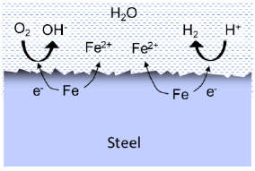
Uniform corrosion is only possible for carbon steel in the brine solution. Several cathode reactions may facilitate this reaction including oxygen reduction and hydrogen reduction. High flow conditions or elevated temperature conditions may favour rapid corrosion in some areas while other areas may be partly covered by rust products (iron oxide), slowing down the process here.
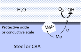
Pitting corrosion is mainly a problem for CRAs that are protected by a passive oxide layer. Even trace levels of oxygen may cause pitting, especially for low alloy grades like 17Cr or EN 1.4401 stainless steel. Corrosion becomes very localised in the pit because the majority of the surface remains passive, at the same time facilitating the cathode reaction. Moreover, the metal-rich and low-pH solution formed in the pit makes the corrosion self-catalytic.
If stainless steel components are coupled to carbon steel, no corrosion will take place because the less noble carbon steel provides cathodic protection at the cost of faster corrosion of this steel. Thus, the risk of severe pitting is only relevant if larger sections of stainless steel (pipework, heat exchangers or pumps) are in-stalled. This is also the reason why highly resistant titanium is used in the plate heat exchangers.
Pitting corrosion and localised corrosion may also occur on carbon steel, if the steel is partly covered by electrically conductive scales such as iron sulphide.
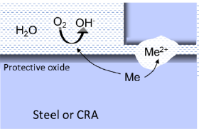
Crevice corrosion have many similarities with pitting, because it is promoted by an oxygen concentration cell between passive and active areas, and by the trapping of an aggressive solution inside the crevice. It is mainly a problem for low alloy CRAs, provided oxygen is present in the brine. Common areas to find crevice corrosion include flange joints, threaded joints or small cavities filled with brine.
Galvanic corrosion occurs when two dissimilar metals are in contact, and at the same time having a liquid connection between the two metals. In geothermal systems, oxygen reduction is the only likely cathode reaction for driving this process. Thus, galvanic corrosion is only considered, if oxygen ingress happens.
The principle of galvanic corrosion is comparable with a battery cell. If the metals are more than 0.1-0.2 V apart in the galvanic series, there is a considerable risk of corrosion of the less noble metal on behalf of the more noble metal. Stainless steel is ~0.6 V more noble than carbon steel in geothermal brine, thereby presenting a risk of galvanic corrosion. If the surface area of the noble metal is much larger than that of the less noble metal, the unfavourable area ratio will lead to extremely rapid corrosion. Due to the high electrical conductivity of the brine, the galvanic element includes surfaces over long distances, making this mechanism particular dangerous in geothermal plants.
For the same reasons, care must be taken when defining the welding procedure for steel tubing in geother-mal plants to avoid galvanic differences between the weld metal and the parent pipe metal. Usually, weld metal is added small amounts of nickel and chromium to optimise the mechanical properties. The addition of such noble elements would typically imply higher corrosion resistance of the weld than the parent metal, but in some situations the effect is opposite leading to a phenomenon known as Preferential Weld Corrosion (PWC). It is always advised to make a prequalification corrosion testing of the welding procedure to avoid this problem before building the plant.
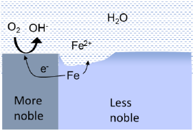
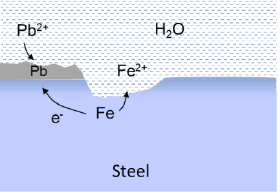
A special form of galvanic corrosion, involving noble metal deposition, can happen in geothermal plants. In certain reservoir types, the brine contains dissolved metal ions, such as lead (Pb2+) in the Bunter reservoirs. And in Germany, dissolved copper ions (Cu2+) has caused galvanic corrosion in one plant.
The tendency for lead deposition increases with increasing temperature and flow rate. Consequently, the production well and tubing are more vulnerable to this form of corrosion than the other sections.
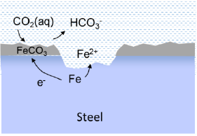
Carbon dioxide (CO2) is a weak acid when dissolved in water and thereby potentially corrosive to steel. The corrosion rate mainly depends on the partial pressure of CO2, which can be high in pressurized systems like geothermal wells. By this CO2 becomes almost an inexhaustible source for the cathode reaction. There is vast experience from oil and gas production, where CO2 dissolved in the produced water is known to cause considerable corrosion. In the Danish geothermal wells only a small fraction of the gas from the production well is CO2 (0.5-3.6%), whereas methane (CH4) and especially nitrogen (N2) make up the majority.
The mechanism of CO2 corrosion involves formation of a partly protecting iron car-bonate film, leading to localised corrosion of the steel. Usually, the corrosion rate increases with temperature up to a maximum at about 70-80 °C. At higher temperature, the carbonate film becomes more stable leading to slower corrosion. Thus, the conditions in the production well (high temperature, high pressure) represent the greatest risk for CO2 corrosion. Flow rate and buffer capacity of the brine are also decisive for the stabil-ity of the carbonate film and the resulting pH at the surface.
Local high flowrates causing turbulence usually increases the corrosion rate of especially unalloyed steel by constantly removing the formed rust layer from the surface. This will happen if pipe bends are too sharp, and in extreme cases, erosion occurs too on the surface. Likewise, sudden pressure changes due to reduced sections in the pipework can lead to cavitation from the impact of collapsing gas bubbles on the surface. Supersaturation with dissolved gasses accelerate this mechanism further. However, usually the design of the plant is made to avoid such flow related degradation mechanisms by following well-established rules for hydrodynamic engineering.
By providing your well's brine composition, it can be compared to other wells in our database using Principle Component Analysis (PCA). PCA is a dimension reduction method that transforms a dataset with many variables into one with fewer (we use 2), while keeping the amount of variability in the data as high as possible. This video gives a short, informative explanation on the basics of PCA.
By plotting the reduced data, similar wells will show up close to eachother. Once you find which well is most similar to yours, the PERFORM website can be used to find comparable wells, and identify any problems encountered in those wells as well as their corresponding solutions.
The severity of corrosion depends on a number of factors, including: the primary driver of the corrosion process (either dissolved CO2, oxygen ingress, the presence of lead ions), the amount of the driver present in the brine, the average flowrate of the brine in the well tubing, the well dimensions, and operating conditions. By filling in the fields in the calculator below, a rough estimate can be made on the amount of corrosion within the well on a yearly basis.
Results are based on worst-case scenario calculation to give an impression of the impact corrosion may cause on particle release. It is assumed that iron forms magnetite (Fe3O4) which is the normal corrosion product in water with almost no oxygen.
CO2 corrosion calculations are based on the Norsok-506 standard. The calculation for oxygen and lead ion driven corrosion are based on simplified stoichiometry.
Please note that these calculations are only here to give a general indication of the corrosion potential. All calculations assume single-phase flow, and do not take into account the interplay between multiple corrosion types, combined corrosion and scaling, or the operating strategy of the well. Decision should not be based on these results, consultation with an expert is required when you think corrosion might be affecting your wells. See the terms of use (top right of page) for more details.
There number of possible strategies an operator can take to mitigate the effects of corrosion. Which are best suited and will have the largest impact depend of course on the type(s) of corrosion present in the well. The list below gives the possible mitigation strategies based on the inputs provided in the "corrosion types" tab.
Click on any of the options to expand it for more details.
DeaerationIt is always of outmost importance to keep the system deaerated, including start-up, operation, shutdown and standstill periods. Air entering the waterfilled system will lead to corrosion of carbon steel and possibly also low-alloy stainless steel.
As a basis, the brine from the reservoir is completely free from oxygen. Thus, possible ingress of air is related to operations in the plant (draining, repair, filter replacement etc.) or faulty and inadequate maintenance of equipment (leaking seals in pumps etc.). Efforts should constantly be applied to minimize the air entering the system from such sources.
During normal operation, the risk of oxygen ingress is usually very small, especially if the system is pressurized. The injection pump represents a potential risk area for air-intake at the seal for the pump shaft due the suction forces. Usually, a special device prevents this from happening by applying a pressure of liquid and nitrogen on the outside of the seal. However, if not operated correctly, oxygen ingress could occur at this location while the pump is running. If the surface plant operates at slight underpressure, the risk of oxygen ingress is even higher and strict procedures should be established, e.g. continuous dissolved oxygen monitoring.
During shutdown for summer periods or repair, special precautions are also required to minimize air, entering the system. In most cases the system remains water-filled without circulation. Some equipment may by disconnected and opened, e.g. filters and heat exchangers. When refilling and reconnecting such equipment, air will inevitably enter the system. Blanketing and pressurizing with inert nitrogen gas are commonly used to displace air as a good practice.
Dosage of oxygen scavengers may be considered to limit the effect of oxygen during shut-down and stand-still depending on the amount of oxygen entering the system. Sodium sulfite, ammonium bisulfite or sodium bisulfite are frequently used in systems such as water injection systems, comparable with the geothermal circuit. Sometimes a catalyst is added in ppb concentration (e.g. cobalt) to speed up the reaction. However, before applying oxygen scavengers the potential risks and side-effects should be evaluated closely. As an example, sulfate and perhaps H2S formed by the reaction with sulfite could promote growth of sulfate reducing bacteria (SRB). Thus, it may be beneficial to add a biocide simultaneously together with the oxygen scavenger.
The only way to prevent corrosion due to metal ions is adding corrosion inhibitors. Corrosion inhibitors form an organic film on the metal surface, thereby obstructing the metal deposition and galvanic reactions from occurring. The efficiency depends on dosage concentration, flow, temperature and surface finish of the steel. It is advisable to conduct corrosion testing in a laboratory before deciding on the inhibitor type and dosage. Continuous corrosion monitoring in the operating plant is also recommended as discussed later.
In the surface plant, where the pressure is relieved, CO2 may come out as a separate gas phase. Removing the CO2 gas from the brine in a de-gasser will be beneficial to avoid corrosion of downstream equipment. However, the resulting increase in pH could on the other hand affect the stability of the brine, leading to scale formation (e.g. calcite). Consequently, a geochemist should be consulted before installing a de-gasser.
Below, a short overview of the result of the corossion well check is given
- CO2: N/A mm/year
- Oxygen: N/A mm/year
- Lead: N/A mm/year
